Work in progress · still being written
RC Car Steering, Designed for Manufacturing
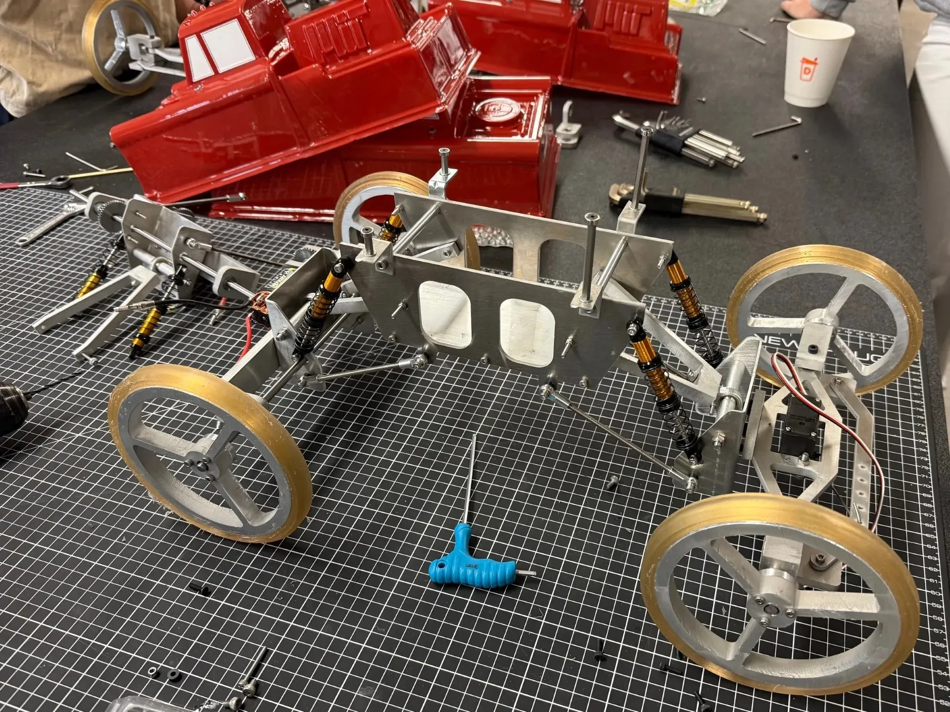
Re-engineering an RC car steering system for batch production. 3D geometries flattened into waterjet-cut aluminum profiles, with tight tolerances only where the mechanism needs them.
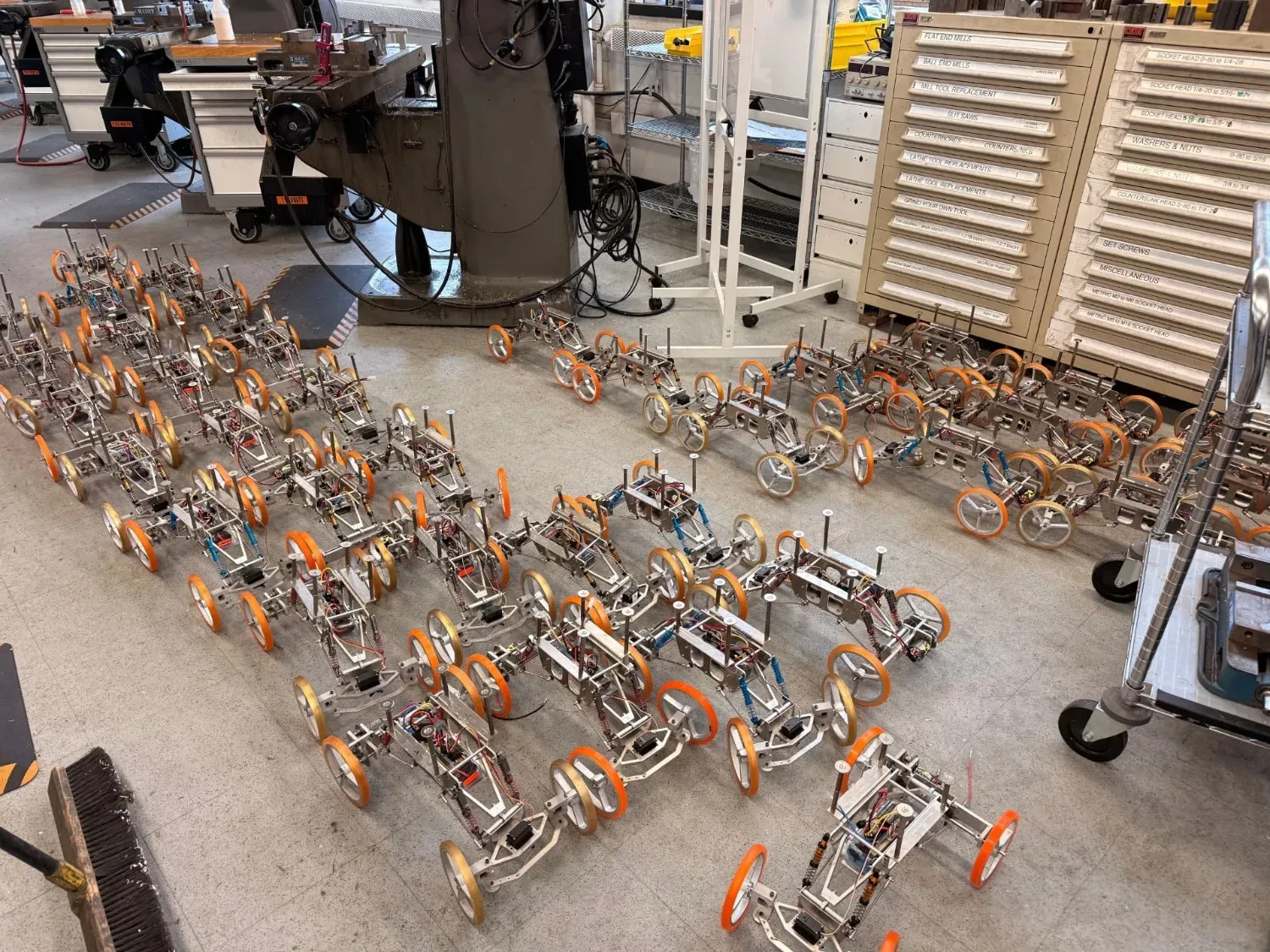
- 8
- Unique components re-engineered
- 1
- Material, aluminum plate
01Inherited design
The inherited steering design worked, but it relied on expensive parts, 3D-printed or complex machined geometry, and unreliable press fits and adhesives. The assignment: take it from "prints on a desktop" to "produces consistently in a shop."
02DFM principles
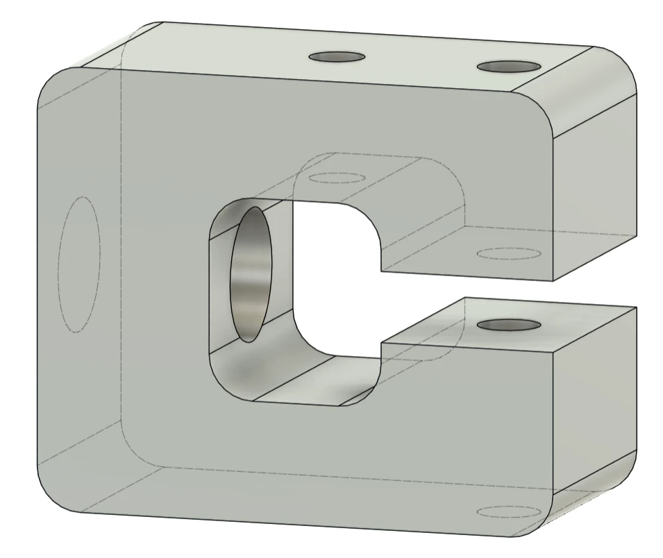
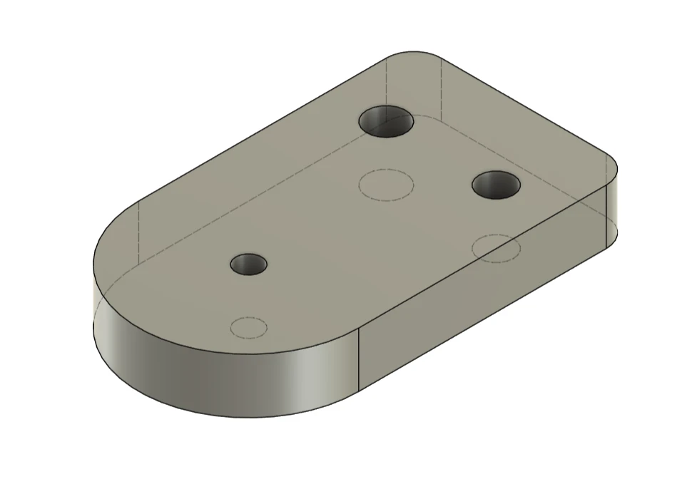
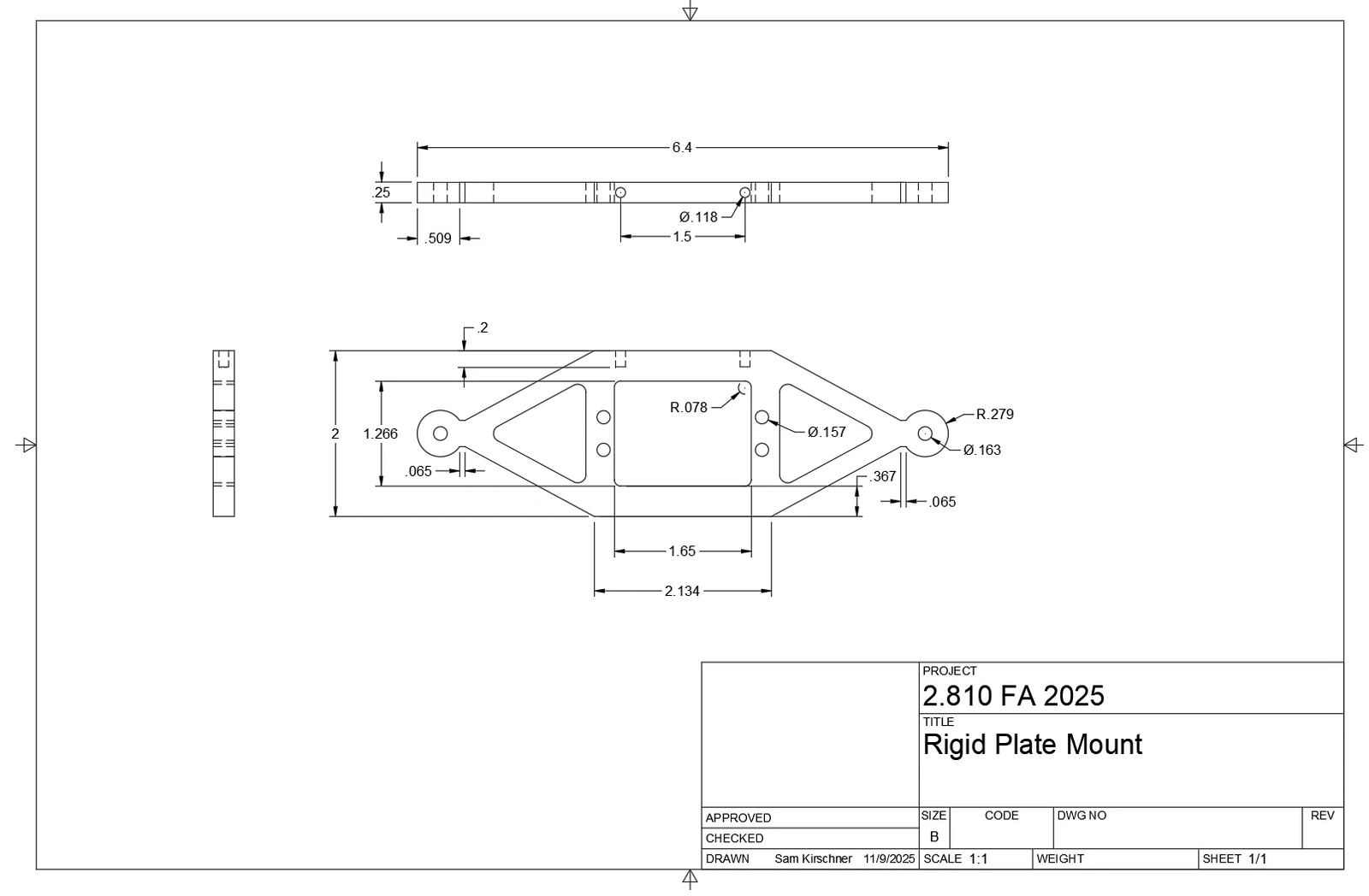
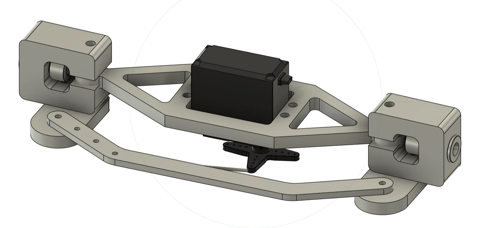
Across the eight unique components (plate mount, rigid linkage, C-joint, steer bars, bushings, shaft collars, wire and servo) we applied one philosophy:
- Flatten to 2D. Complex 3D geometry re-modeled as flat profiles cut on the waterjet and assembled with simple fasteners.
- Machine only critical features. Tolerance and machine time spent on bushing bores and mating faces, not cosmetic surfaces.
- Standardize joining. Bolted connections instead of press fits and adhesives wherever possible.
- One material. Aluminum plate stock for predictable, repeatable machining.
03Process planning
Each part got an explicit operation sequence. The plate mount: waterjet the profile and holes, drill the top holes to tolerance, face the back edge on the mill, then drill and tap.
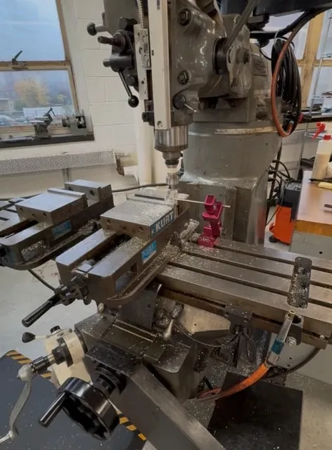
The C-joint is the showcase part: waterjet profile, face front and back, drill and ream the bushing bore, face the interior surfaces, then press-fit and ream the bushing to final size. Each datum is established before the features that depend on it.